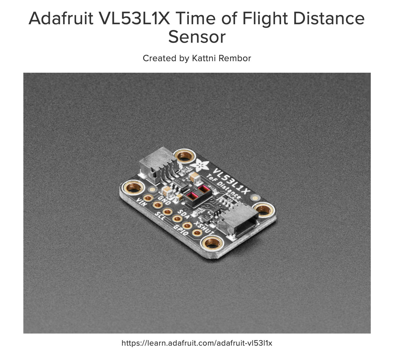
Overview
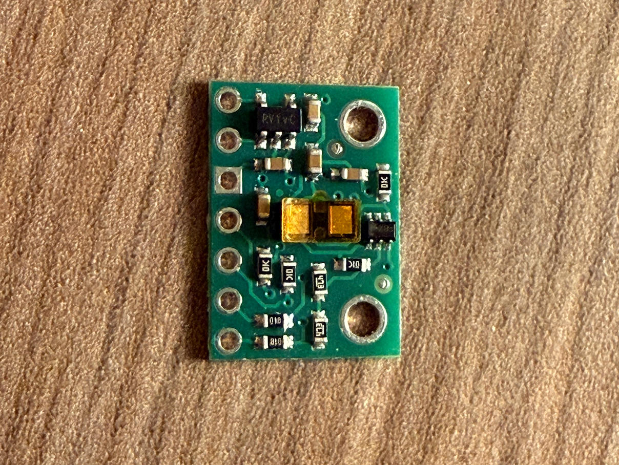
Considering what my final project needs, I decided to add another PCB module this week. This assignment focuses on creating a distance sensor that measures physical distance and displays the readings on a screen. The sensor I chose is the VL53L1X, which I selected for its clear pin labeling. After researching how this sensor works, I determined that I only needed four pins to make it functional: VDD, GND, SDA, SCL.
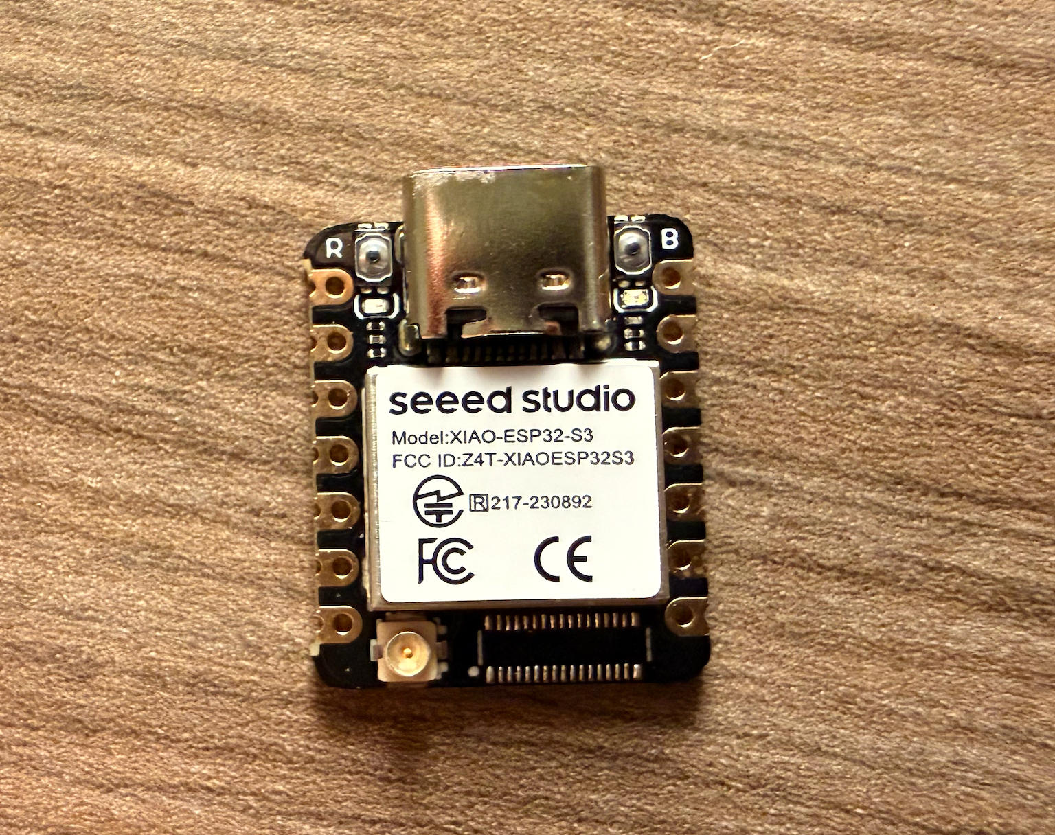
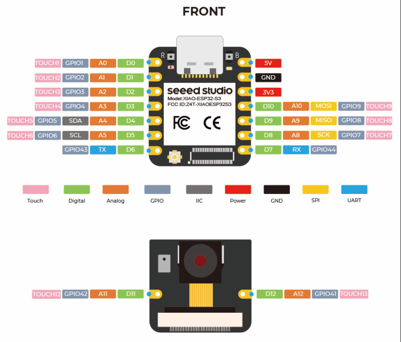
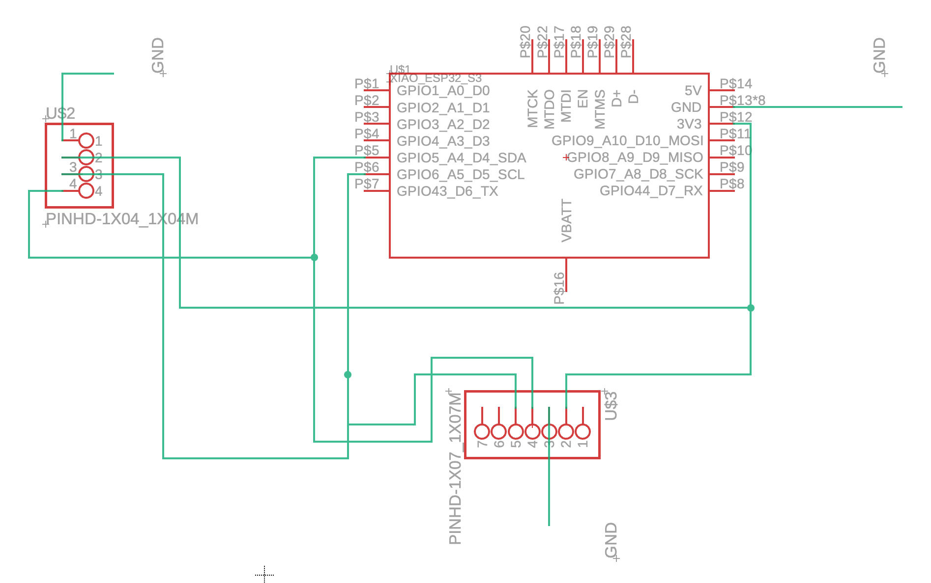
I downloaded the XIAO ESP32S3 pinlist and VL53L1X pinlist to guide my PCB design.
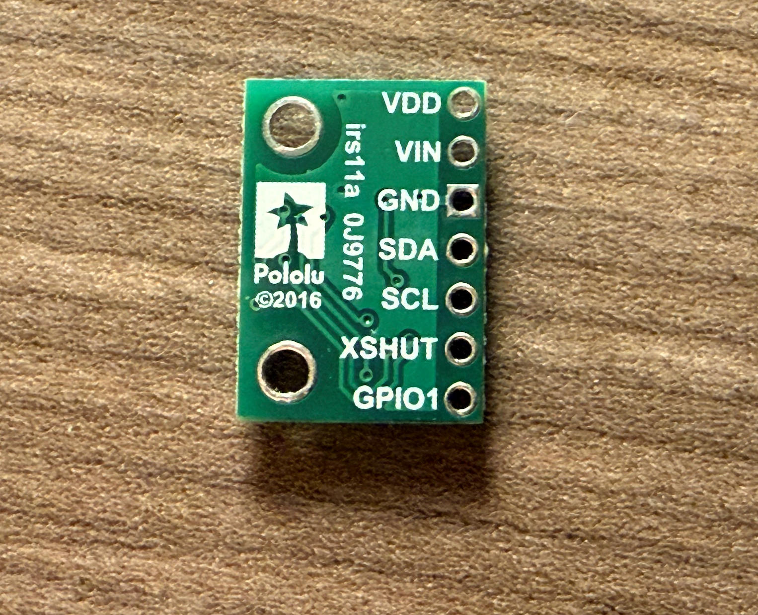
VL53L1X Pin Overview
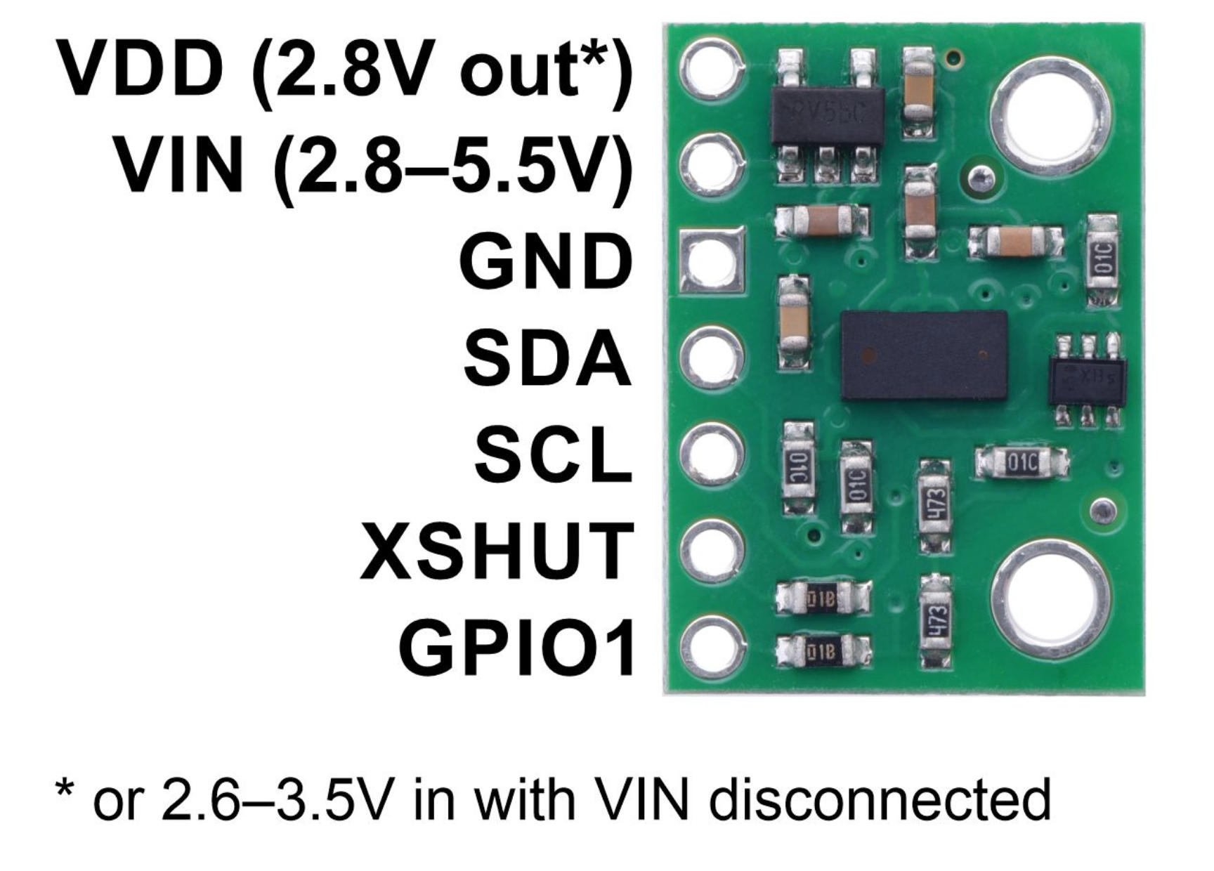
The VL53L1X has six pins. Here's what each one does:
VIN — Power input, typically 3.3V or 5V.
GND — Ground reference. Must be connected to the microcontroller's GND pin.
SCL — I²C clock line. Connect to the microcontroller's SCL pin. The microcontroller controls the clock pulses on this line.
SDA — I²C data line. Connect to the microcontroller's SDA pin. All data (commands and readings) flows through this line. Together, SCL and SDA form the entire I²C communication interface.
GPIO — A general-purpose output from the sensor. This pin is optional and can be used as an interrupt output, for example.
XSHUT — Shutdown pin (active-low hardware reset). Pull LOW to shut down the sensor, or pull HIGH (3.3V) to wake it up.
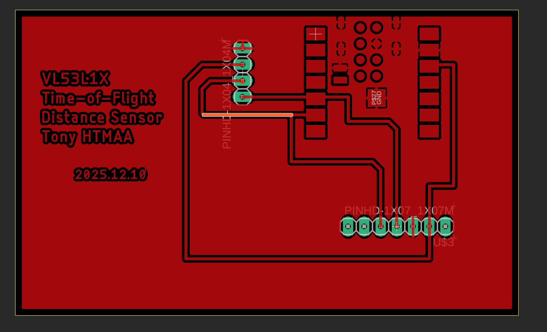
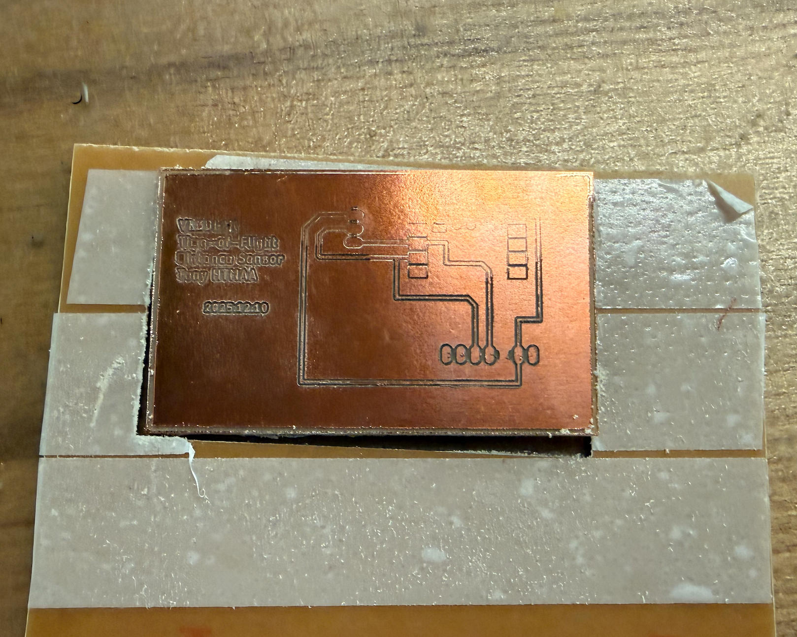
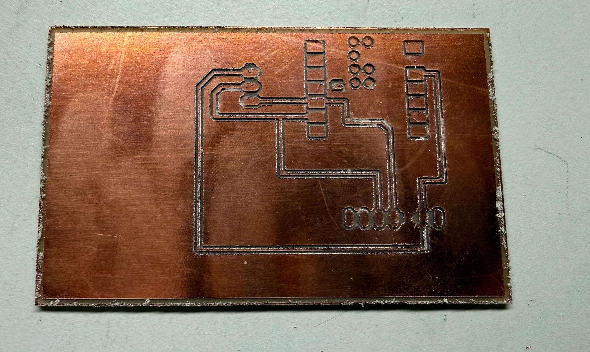
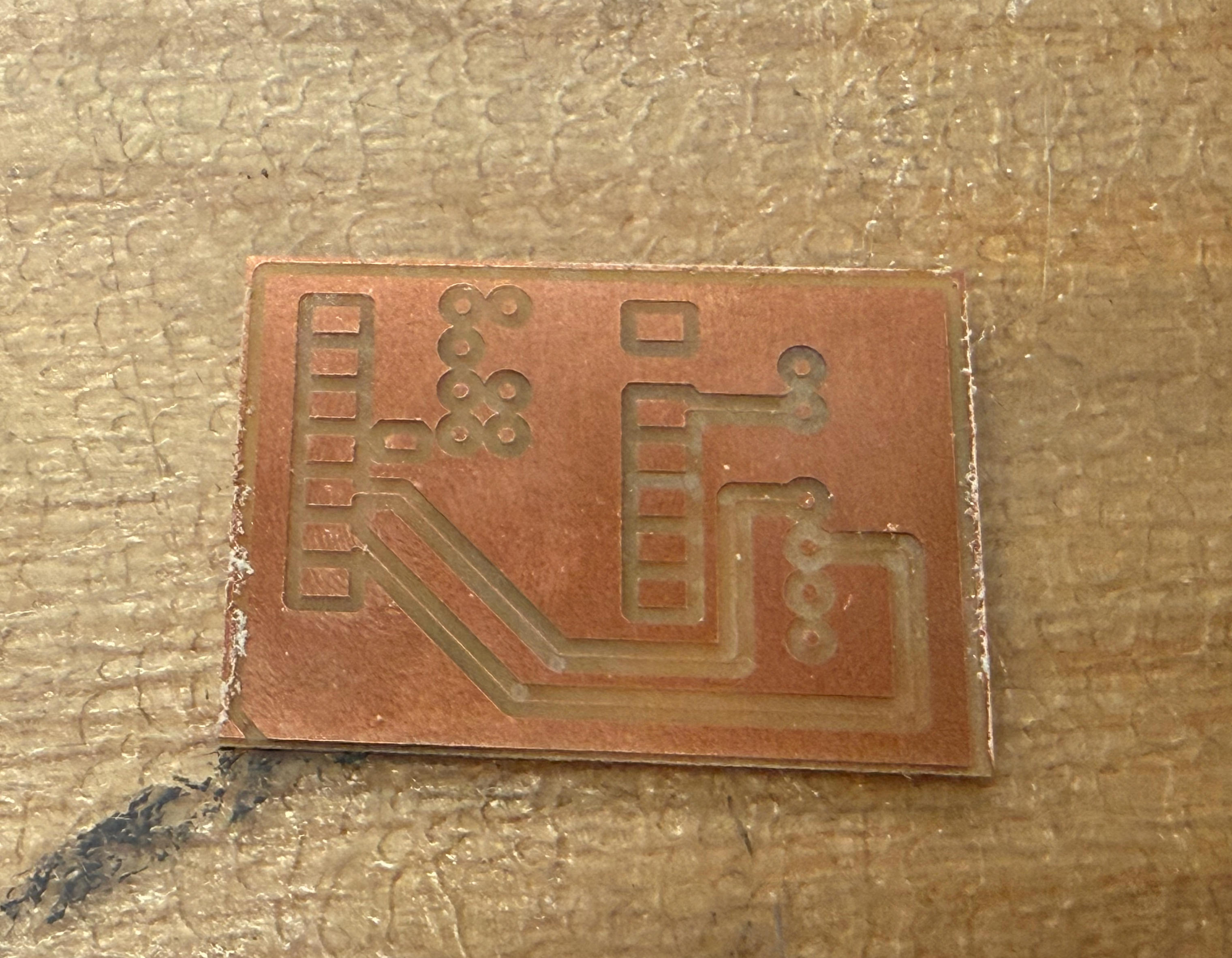
PCB Design
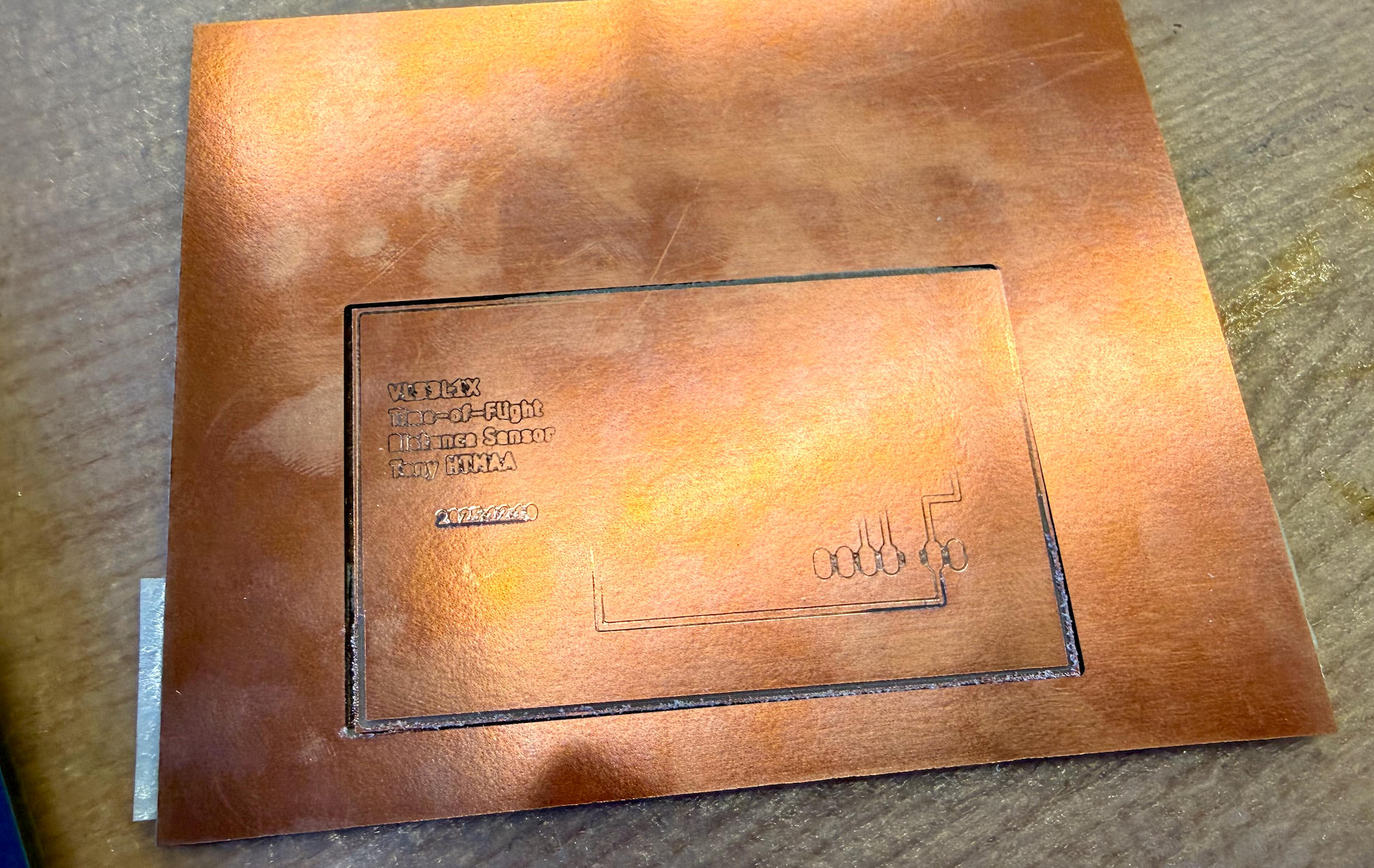
Board Milling
Files
Programming & Testing
Before programming, I needed to install the VL53L1X library.
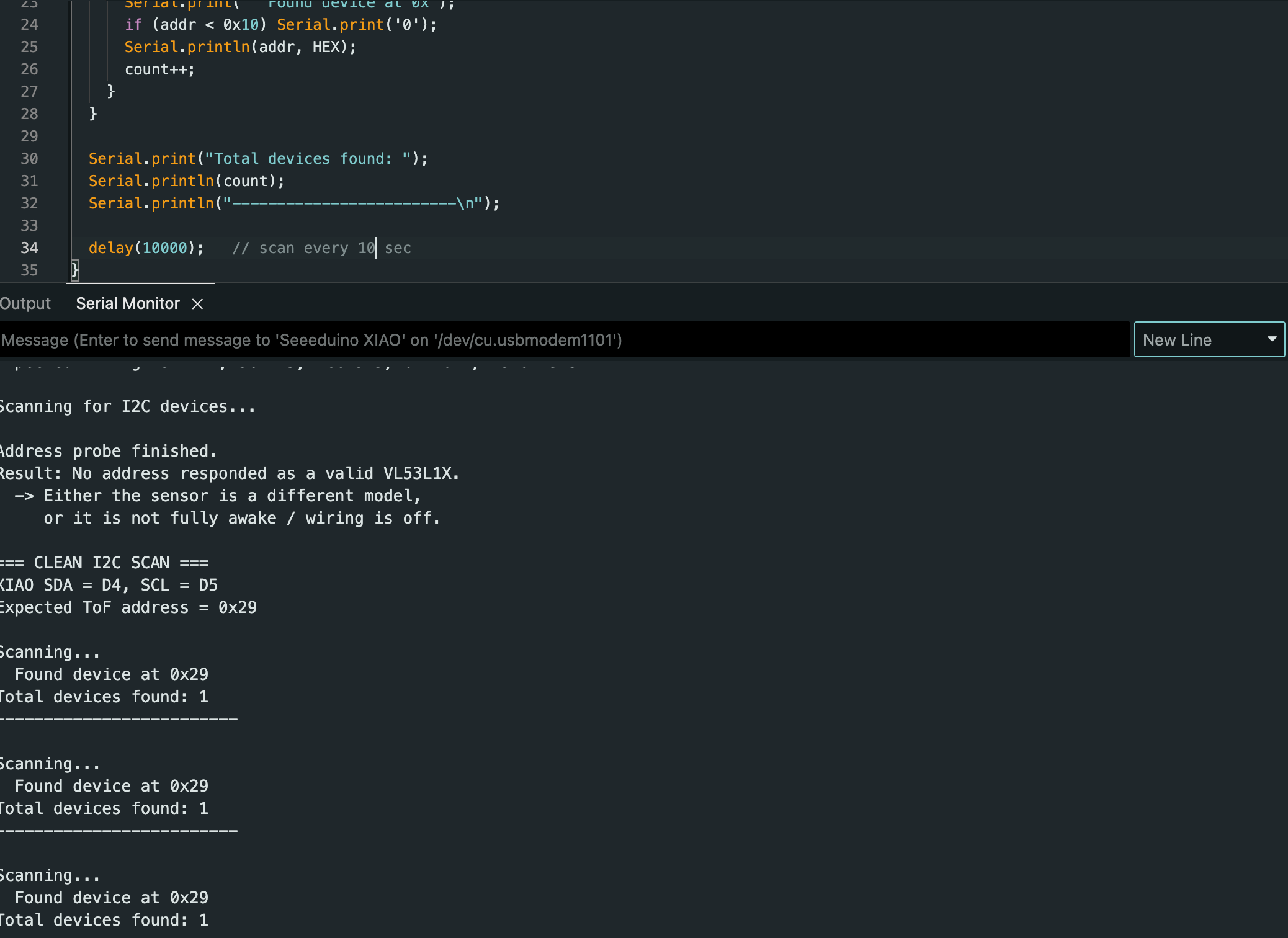
During initial testing with simple wire connections, I encountered an unexpected problem: I wrote a program to scan for I²C devices, and the result shocked me—the system detected 120+ devices! After research, I determined that my wire was too long. Long wires cause HIGH and LOW signals to drift into undefined floating states, creating noise. Once I switched to shorter wires, the problem disappeared and I detected only one device at address 0x29.
#include <Wire.h>

// Change these if you're on a board where you can re-map I2C pins (ESP32, etc.)
#ifndef SDA
#define SDA -1
#endif
#ifndef SCL
#define SCL -1
#endif

static const uint8_t VL53_ADDR = 0x29;

// ---- Low-level I2C helpers for VL53L1X register access ----
// VL53L1X uses 16-bit register addresses.
bool writeReg16(uint8_t addr, uint16_t reg, uint8_t value) {
  Wire.beginTransmission(addr);
  Wire.write((uint8_t)(reg >> 8));
  Wire.write((uint8_t)(reg & 0xFF));
  Wire.write(value);
  return (Wire.endTransmission() == 0);
}

bool readReg8(uint8_t addr, uint16_t reg, uint8_t &out) {
  Wire.beginTransmission(addr);
  Wire.write((uint8_t)(reg >> 8));
  Wire.write((uint8_t)(reg & 0xFF));
  if (Wire.endTransmission(false) != 0) {
    return false;
  }

  int n = Wire.requestFrom((int)addr, 1);
  if (n != 1) return false;

  out = Wire.read();
  return true;
}

void i2cScan() {
  Serial.println("=== I2C scan ===");
  int found = 0;

  for (uint8_t a = 1; a < 127; a++) {
    Wire.beginTransmission(a);
    uint8_t err = Wire.endTransmission();
    if (err == 0) {
      Serial.print("  Found device at 0x");
      if (a < 16) Serial.print("0");
      Serial.println(a, HEX);
      found++;
    }
  }

  Serial.print("Total I2C devices: ");
  Serial.println(found);
  Serial.println("=== I2C scan end ===\n");
}

void setup() {
  Serial.begin(115200);
  delay(800);
  Serial.println("\nVL53L1X I2C + ID Test\n");

  Wire.begin();
  Wire.setClock(400000);

  i2cScan();

  Serial.println("Checking for device at 0x29...");
  Wire.beginTransmission(VL53_ADDR);
  uint8_t err = Wire.endTransmission();
  Serial.print("  endTransmission returned: ");
  Serial.println(err);

  if (err != 0) {
    Serial.println("\n❌ No ACK from 0x29.\n");
    return;
  }

  Serial.println("✅ 0x29 ACKed.\n");

  Serial.println("Reading Model ID (reg 0x010F)...");
  uint8_t modelId = 0;
  bool ok = readReg8(VL53_ADDR, 0x010F, modelId);

  if (!ok) {
    Serial.println("❌ Failed to read Model ID.");
    return;
  }

  Serial.print("✅ Model ID read: 0x");
  Serial.println(modelId, HEX);
}

void loop() {
  delay(3000);
  i2cScan();
}
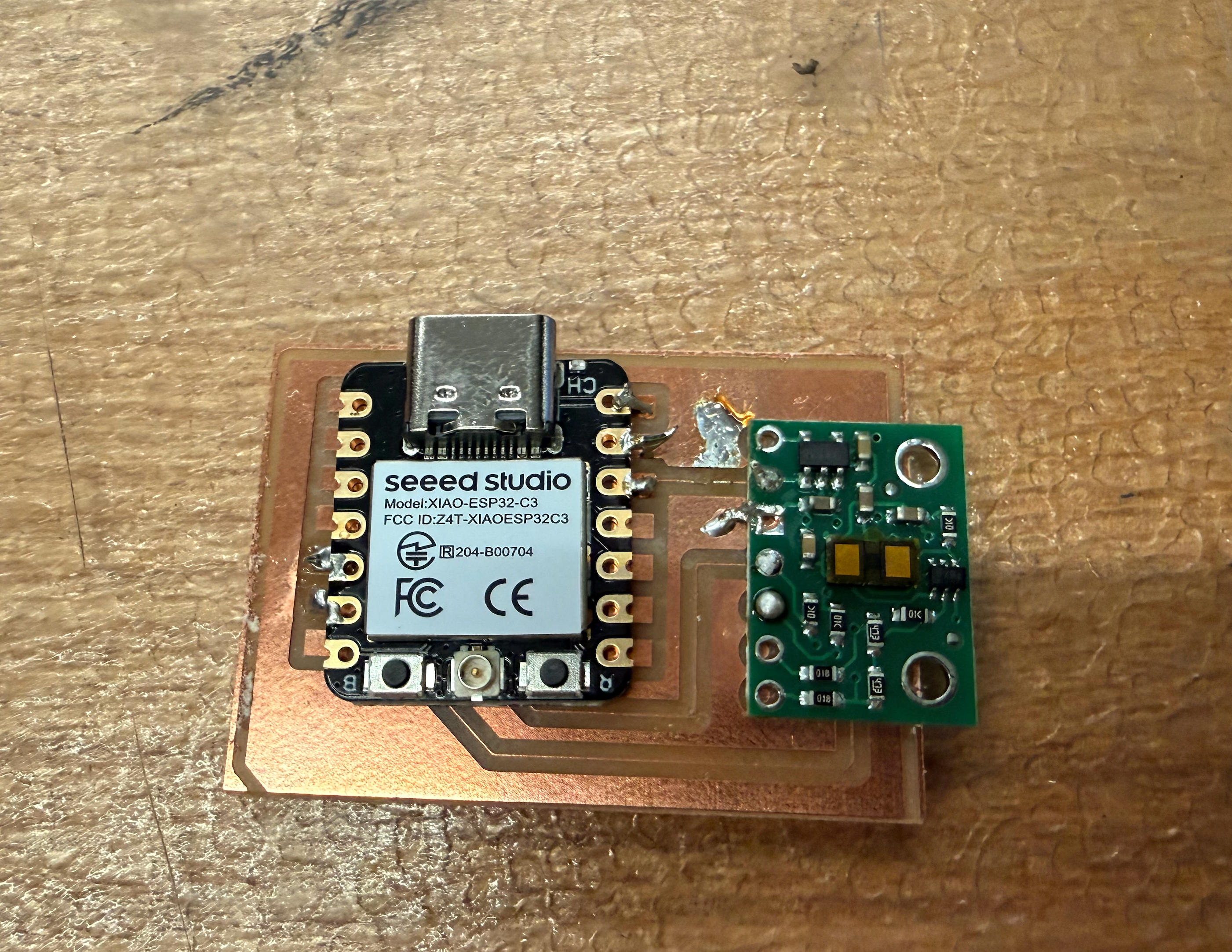
Testing the Sensor
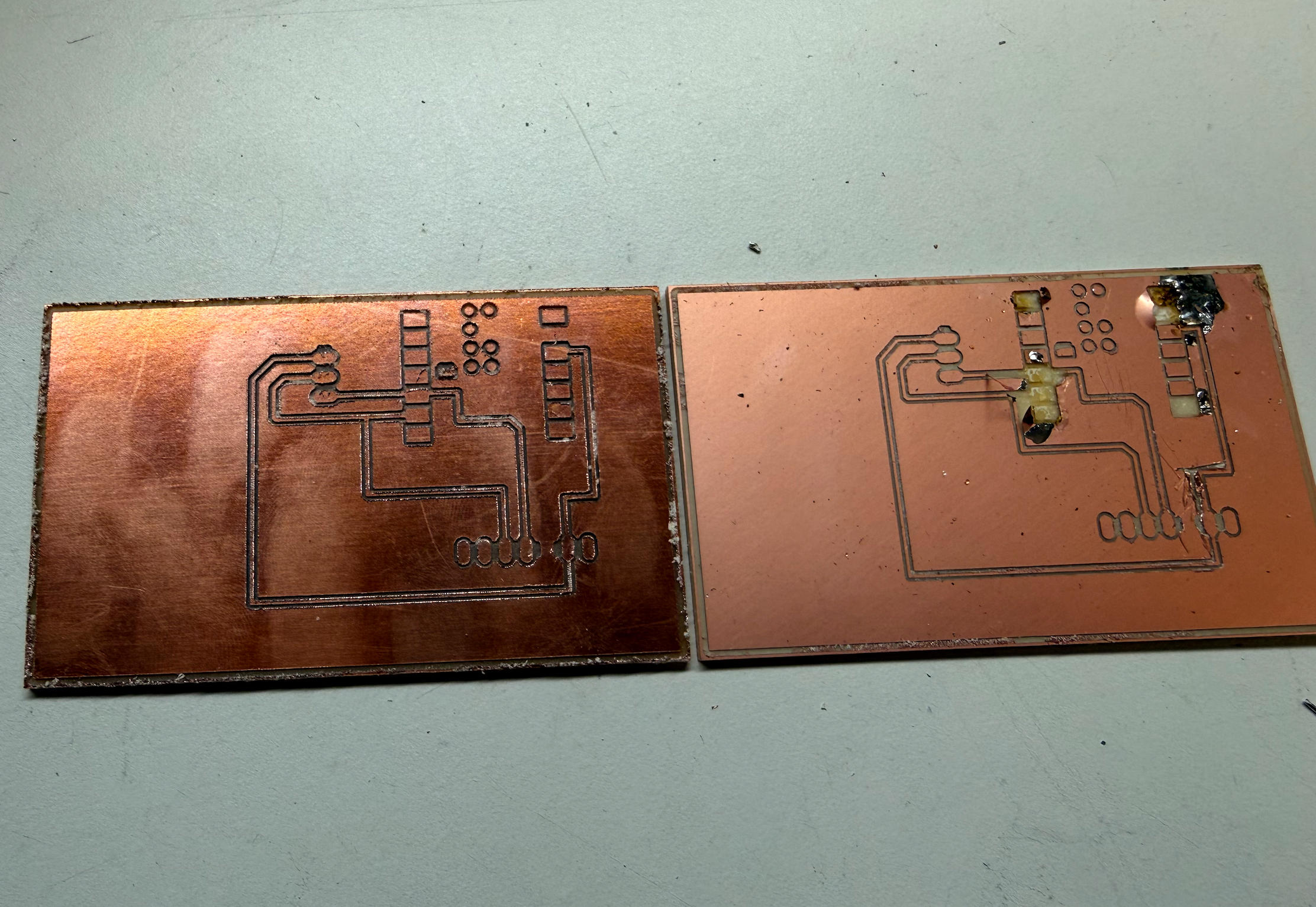
Since the connection was simple and I had experienced a major setback while soldering the board, I decided to first connect the electronics with temporary wires and write a test program to verify the sensor works. The results were surprisingly smooth—it worked, though with a few caveats I'll discuss shortly.
Initial Observations
1) Readings showed small variations (mm-level jitter)
Even when the sensor was placed on a stable table measuring the distance to the ceiling, the returned values were not identical each time. The readings were largely consistent, but each measurement varied by a few millimeters. This suggests the sensor has a small but noticeable measurement error or noise under real conditions.
2) "Zero" readings occurred before physical contact
When I moved my hand close to the sensor, it reported zero distance before physically touching it.
I could get a reading of 0 even when my palm was approximately 3–4 cm away.
This suggests there may be a minimum measurable range or clamping behavior—the sensor might report 0
below a certain threshold distance rather than reporting negative values. In other words,
the displayed value may behave like: max(0, real_distance - threshold).
Display Integration
#include <Wire.h>
#include <Adafruit_GFX.h>
#include <Adafruit_SSD1306.h>

#define SCREEN_WIDTH 128
#define SCREEN_HEIGHT 64
#define OLED_RESET -1
#define OLED_ADDR 0x3C

Adafruit_SSD1306 display(SCREEN_WIDTH, SCREEN_HEIGHT, &Wire, OLED_RESET);

void setup() {
  Serial.begin(115200);

  // Use board default I2C pins
  Wire.begin();
  Wire.setClock(100000);

  if (!display.begin(SSD1306_SWITCHCAPVCC, OLED_ADDR)) {
    Serial.println("SSD1306 init failed");
    while (true) delay(10);
  }

  display.clearDisplay();
  display.display();

  Serial.println("OLED initialized");
}

void loop() {
  static uint32_t counter = 0;

  display.clearDisplay();

  // Visual proof it works
  display.drawRect(0, 0, 128, 64, SSD1306_WHITE);
  display.fillRect(5, 5, 30, 20, SSD1306_WHITE);

  display.setTextColor(SSD1306_WHITE);
  display.setTextSize(2);
  display.setCursor(45, 10);
  display.println("TEST");

  display.setTextSize(1);
  display.setCursor(45, 40);
  display.print("Count: ");
  display.println(counter++);

  display.display();
  delay(200);
}